Surface Unit Reference Source
The surface Subsonus unit requires a source of time, position, velocity and heading data to function. This data can be provided by either a GNSS Compass or a GNSS/INS. There are three options available for the reference source.
The recommended source is the Advanced Navigation GNSS Compass which will give the best results. Many survey ships will have an existing high accuracy GNSS/INS in which case they can use either an Advanced Navigation GNSS/INS or Third Party GNSS/INS or GNSS Compass option.
When the Advanced Navigation GNSS Compass is used as the reference source, Subsonus operates in full GNSS/INS mode. When a third party GNSS/INS or GNSS Compass is used, Subsonus will operate in AHRS mode and not perform any further processing on the reference data.
Advanced Navigation GNSS Compass

Advanced Navigation GNSS Compass
Advanced Navigation manufactures an all in one GNSS Compass system powered using PoE (Power over Ethernet) that is an ideal reference source for Subsonus. The Advanced Navigation GNSS Compass is supplied with the Subsonus Evaluation Kit. For detailed installation instructions, refer to the Advanced Navigation GNSS Compass Reference Manual.
Mounting Options
The GNSS Compass accepts a standard 5/8” survey mount or 4 x M8 panel mount bolts, see Advanced Navigation GNSS Compass mechanical drawing for mechanical details.
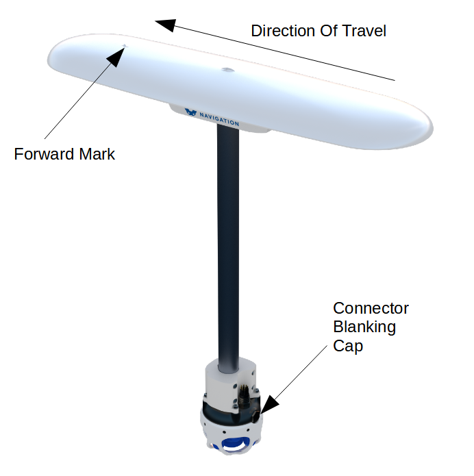
The ideal mounting position for the GNSS Compass is on top of the surface Subsonus pole. The mounting alignment between the Subsonus and the GNSS Compass is extremely important, see Advanced Navigation GNSS Compass mounting
Mounting Position
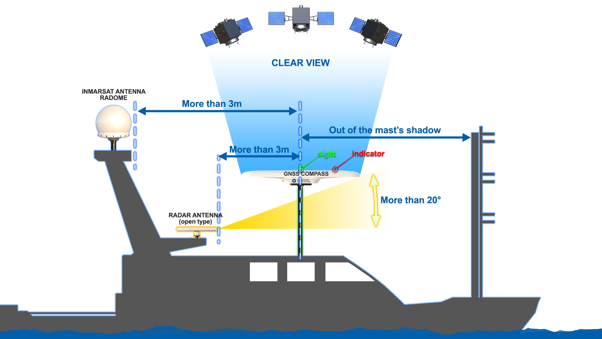
When planning a mounting location for GNSS Compass, refer to Mounting location example, and be mindful of the following recommendations.
-
Mount the unit in clear view of the sky
-
Mounting the unit at least 3m from transmitting devices, otherwise they may degrade heading performance due to interference.
-
Mount the unit in an area that will not exceed the rated temperature range, and with minimal temperature fluctuations.
-
Mount the unit away from high levels of vibration where possible.
-
Mount the unit at least 10 cm away (and preferably as far as possible) from sources of dynamic magnetic interference such as high current wiring or large motors for best performance.
Mounting Alignment
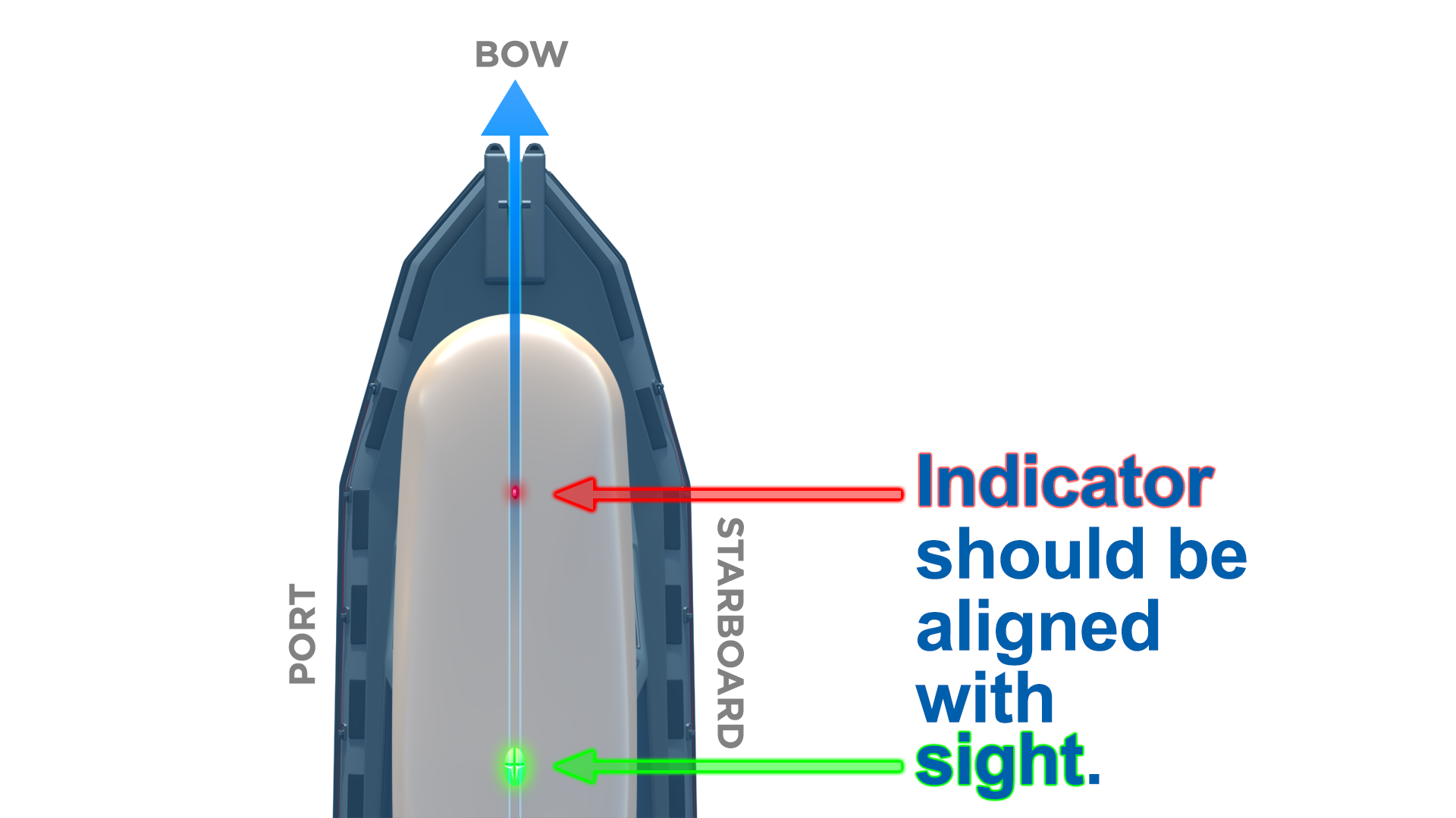
The GNSS Compass should be mounted with its forward indicator pointed in the direction of travel of the vehicle. The connector blanking cap on Subsonus should be pointing in the opposite direction of the GNSS Compass forward indicator, see Advanced Navigation GNSS Compass mounting. It is critical to accurately align the GNSS Compass with Subsonus, and also to align the GNSS Compass unit with the forward direction of the vessel, see GNSS Compass Alignment.
Note: The Subsonus will not function correctly if the GNSS Compass is not correctly aligned to the Subsonus unit. The Subsonus will also not function correctly if the GNSS Compass is not correctly aligned to the vessel. it is extremely important to accurately measure any offsets encountered.
Offset Measurement
Regardless of whether the recommended mounting has been performed, there will be a position offset (lever arm) between the GNSS Compass and Surface Subsonus.
In order to calculate the lever arm between the GNSS Compass for positioning of the Subsonus, the position offset data must be entered during system configuration. Without this information, the position data for the Subsonus will be incorrect. See Subsonus Surface Unit Reference Source Aiding.
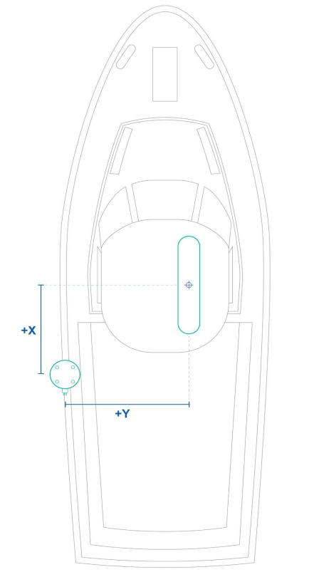
Once both units are mounted to the vessel, the offset from the Subsonus to the base of the GNSS Compass must be accurately measured. If Subsonus and GNSS Compass share a pole for mounting, there will only be an offset in the Z direction.
Toward the bow of the vessel is positive X, to the starboard is positive Y and up is negative Z. See The Sensor Co-ordinate Frame and GNSS Compass and Subsonus Offset direction for more information.
Configuration
Once plugged into the same network, Subsonus will automatically recognise the presence of an Ethernet GNSS Compass, as surface Subsonus units are automatically configured to look for the GNSS Compass data stream using the ANPP. To confirm that the surface Subsonus has recognised and configured the GNSS Compass, open the Subsonus web UI. On the main view, the GNSS Compass should be visible on the Device list on the left hand side of the map. See GNSS Compass shown in device list.
The GNSS Compass will also appear under “Configuration”→“Devices”. See GNSS Compass appearing in active devices
If the GNSS Compass does not appear in Active Devices, it must be manually configured. See Subsonus Surface Unit Reference Source Aiding for information on how to add a new device.
Advanced Navigation GNSS/INS
Subsonus supports any of Advanced Navigation's GNSS/INS products. Subsonus will automatically detect the Advanced Navigation device as it does with an Advanced Navigation GNSS Compass. An operator will be required to configure offsets between the devices before use, see Device Configuration.
Third Party GNSS/INS or GNSS Compass
Third party GNSS/INS and GNSS Compass systems work with Subsonus if they can output NMEA messages GPZDA, GPGGA, GPVTG and GPHDT. It is recommended that the third party system is able to output NMEA messages at 10Hz, although slower speeds are possible.
If the third party system has an Ethernet interface, it should be configured to send the NMEA messages to Subsonus over a TCP port, please see Interfacing with Subsonus.
Note: It is recommended to synchronise the third party device and Subsonus with a PTP or NTP time server

